2.2 LATHE EXERCISE
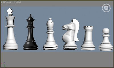
Using the ‘ref-chess.jpg’ file create a set of 3D chess pieces.
To do this you will need to add the above file as the background image to the FRONT viewport. To do
this:
1. Click the VIEWS menu, then VIEWPORT BACKGROUND | VIEWPORT BACKGROUND
2. Using the FILES button select the above file and ensure MATCH BITMAP is selected in the
ASPECT RATIO panel.
3. Also ensure LOCK ZOOM/PAN is ticked so that the image reacts to those commands and
moves with the viewport
4. The image now appears as a background to the viewport
5. Press G to disable the grid if required
6. Now draw around the PAWN using straight lined SPLINES, draw a rough outline to start with,
as you can refine it later. When complete add a LATHE modifier to create a 3D shape
=LATHE EXERCISE
The first exercise was to model the chess set with the LATHE tool.
First started off with the easiest pawn.
I imported the chess set picture as the background, which helped a lot with the whole modelling process.
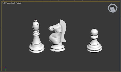
Pawn was really simple, only drew the outline along half of the its shape.
Then select LATHE in the modifier list. DONE!
Next I chose to do the bishop, which was also similar to the pawn, Outlined half of the shape then used the LATHE tool.
Only I had to do one more process, which was to subtruct a little "cut" on the top.
It was simply done by the Boolean subtraction method.
In the following, I moved forward to create the most complicated piece, the Knight.
First of all I outlined the shape roughly around the main part of the horse.
Then adjusted the vertexes with the move tool to fit the shape in a better way.
After that I had to add more vertexes within the shape, I did that by using the REFINE button in vertex tab.
connect vertexes together, then selected those inner vertexes and "pulled" them with the move tool on the top view mode. so it would become more "3D".
I couldn't capture many screen shot during the modelling process, because the camera was very awkward especially with the complicated vertexes.
After I had pull the inner vertexes, I selected them and used the tool called BEZIER CONNER in order to adjust the tone of the horse and the edges where the other half would connect.
Next was to use the SURFACE tool, so that the area formed by these vertexes would be created into the 3D shape.
But this step, I had only done half of the horse, the second half was to be done by another tool called SYMMETRY tool in the modifier list.
Last I ended up with a complete 3D shape of the horse.
Only without the "Horse's Hair", then I had to refine more vertexes close to the centre of its back, in order to form the polygon.
Last step, was to convert it into editable poly and extrude. Then I resulted with the top half of the knight.
The botton half was exactly the same technique I used with the pawn, so I wouldn't repeat myself again here.
The rook was the similar technique as the pawn, but only with addition of using the EXTRUDE tool to create the battlements
Bishop, Knight, Rook, Pawn DONE.
The king was exactly the same as the pawn.
First outlined the base shape, then used LATHE tool to "spin" it around.
Last added the top cross with the 2Dto3D EXTRUDE method.
Queen was done with exactly same technique as the Rook.
Exercise 1: Done.
================================================================
4 VIRTUAL STUDIO EXERCISE
THREE-VIEW EDITING
This is a very useful technique for creating 3D models from technical drawings or character sketches,
and involves having a different view of the drawing in each viewport. These background images can
then be used as a guide in defining the dimensions of your model. However, if you are using different
images in different viewports they all need to be the same scale so may require some image
manipulation in order to ensure this.
=VIRTUAL STUDIO EXERCISE
This week the second exercise is practicing the technique of using 2D images to assist the 3D modelling.
I have watched a few 3Ds max tutorial on youtube before, and this technique was one of my favourite that I watched. Only that in the tutorial, there were only the side and top view images, and the side view image was put in the centre of the top view, which was forming a cross instead of a box.
This week exercise, I decided to try out and use this technique on modelling one of my assignment choice, so that I could spend extra time to reach perfection on this model.
Because they were all planes this week, so I chose to start with the X-wing from star war.
I found the graphical design image from the below website.
Reference:
http://www.obh.snafu.de/~madley/starwars/Tech.html
After I had cut and re-sized the image, I resulted with the three directions images, therefore I put them in a box as below.
I first started with a box with relatively high polygons and started to move vertexes to fit the shape of the plane.
I first expected with high polygons, I could fit the shape easier, as there would be more vertexes.
But then I realised, if moving vertexes just by "free hand", they could hardly be kept as straight lines and shape corners, which ended up like the below image. So that it was something I experienced, but at the same time, perhaps this "error" could be used in some other "wobbly situation" ?
 After that
After that I modeled it with minimum polygon shapes, and decided to break complicated shapes into several simpler shapes instead of one with high polygon.

In this part, convert shapes into editable poly was important, therefore I could drag vertexes around to fit any shape.
I also used massive amount of Boolean subtraction technique to create the "machine patterns".
Even though patterns could be added by the materials, but creating them in this step would give a more solid and realistic effect especial there would be a difference in close-up shots.
Cutting on a non-flatten surface was much more difficult, but I figured out my way of modelling them, which was to copy the same shape and re-sized it into a little larger or smaller, then I would cut on the larger shape, and the smaller shape would become its core/base shape.
On this model, I also used methods such as extrude, outline, chamfer etc.
Eg: extrude, outline on the end of below engine.
Next I carried on to the upper surface of the wing.
Not all the patterns were created by Boolean-subtraction, half of them were also created by adding the direct shapes on the surface.
Also there was another way to add patterns, such as adding the air vents, I didn't have to create the exact shapes, but by Boolean-subtraction method, I could have shapes of three rectangles patterns for example.
Then just by pulling the vertexes out, I could make them look like below.
And pulled the other end of the vertexes, they would look like air vents without adding extra primitives.
Then I copied and rotated the wind to the other side to become the other wing, as this one faced upside down, I had to create more patterns for this area.
(Note that I did not follow exactly as the 2D images, because on the design, wings were quite small and shorts for the long front of x-wing, but it was used when started all the basic with the images.
Also it helped me when I had to adjust the angles of the wings.)
Next I used the mirror technique to mirror the wings on the other side.
Instead of using the mirror tools directly, I chose to use the mirror option from the modifier list, this gave me a more freely option, as they were editable, I could remove or edit this effect anytime later.
After all the above, the front of the plane was too simple and plain, so I moved on to add patterns for it.
In fact this step was the hardest in the whole modelling process, because the front of the x-wing had angles in every directions, it did not have any perfect 90 degrees angles,so creating patterns was the hardest on such surface.
I had to keep using the move tool to edit vertexes even on the shapes I use to subtract with (like the blue boxes below, they were not a perfect rectangular boxes. Not 90 degrees on every corners.)
Last was the body of the x-wing.
One of the point I would like to mention was, I first started to view the model with the edged faces and Shaded options, but then it started to get too complicated to be viewed, so that I could only view it with realistic option.
Last, the basic modelling of the x-wing was finished.
Note that the R2-D2 type robot was missing on the x-wing, as it would be my second model on the assignment, plus I would need them to be separated in the animation.
Front
Pilot seat area, I might need to add the exact details later on if it would be needed in my story line.
Body of x-wing, with R2-D2 type robot insert place.
The back of the x-wing
EngineUpper face of the wing
Part of the wing, next to the engine
Lower face of the wing
Gun
Complete model
The Incom T-65 Starfighter - X-wing !

Overall, I was very please with the final model of the x-wing.
I spent a lot more extra time on this model, as it was both the week exercise and assignment.
I had concerned about the adding material step for this model, but then I believed, it would need much materials on, as it already had all the patterns etc on.
File will be attached in the Week 6 assignment disk.
Exercise 2: Done


No comments:
Post a Comment